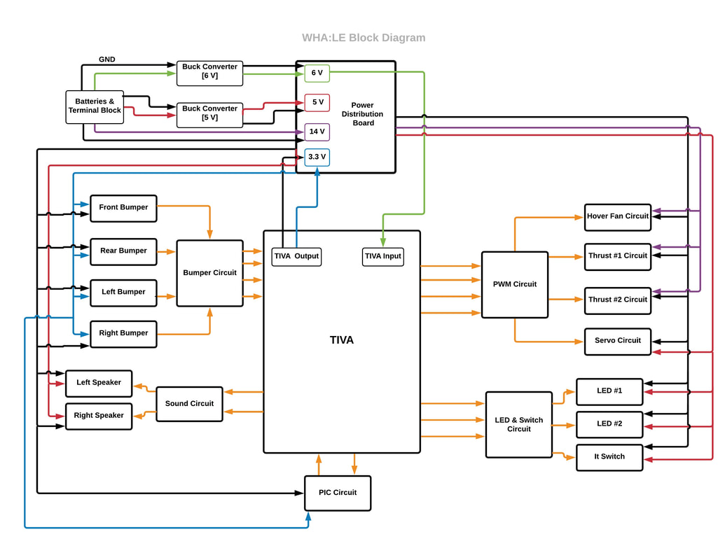
Block Diagram
Schematics
TIVA pinouts
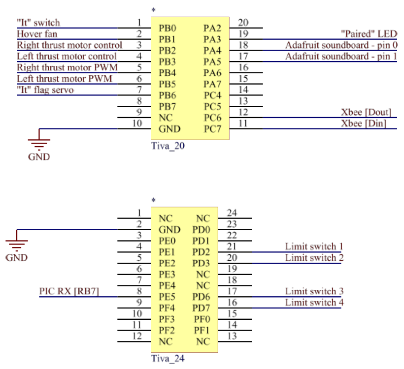
The TM4C123G LaunchPad Evaluation Kit is a low-cost evaluation platform for ARM Cortex-M4F based microcontrollers from Texas Instruments. The TIVA is used to control all aspects of the project.
XBee Radio

The DIN of the XBee was connected to the TX line from TIVA to receive requests from the TIVA. The DOUT of the XBee was connected to the RX line from TIVA to transmit requests to the TIVA. The XBee was powered off of 3.3V.
Hover fan

We powered our thrust fan off of 14V, which ultimately required its own set of batteries. The MOSFET provided a convenient way to turn the fan on and off using a logical high or low from the TIVA pin.
Soundboard, audio amplifier, and speakers

All of the components in this circuit were powered off of 5V. Pulling certain pins low (the ones connected to PA4 and PA5) on the Adafruit soundboard allowed audio files to be played. The R and L outputs of the Adafruit soundboard were then fed into the R and L channels of an audio amplifier. Common (between the channels) was grounded. The outputs of the audio amplifier were connected to two, 3-Watt speakers.
Mics & FM radio transmitter

We used two MAX9814 Electret microphones to detect sound from the left and the right sides of the craft. Both microphones were powered off of 5V, and the output of the mics was connected to the left and right channels of an audio jack, which had an FM transmitter plugged into it. When set to the proper channel, the FM transmitter would convey the audio captured at the mics to the FM receiver.
Thrust motors

The thrust motors, powered off of 14V, required too much current at maximum duty cycle to be run off of the TLE drivers from 218B. We decided to sacrifice direction control for current capability. Each motor was placed in series with a snubbing diode. We PWMed the gate of each MOSFET to achieve our desired duty cycles.
LEDs [Paired, Singing]

We had two status LEDs. One for displaying the "paired" status was connected to the TIVA and the other for displaying when the WHA:LE was singing was connected to the PIC. The LEDs were hooked up directly to the MCs with current limiting resistors in series.
"It" switch

A single pole double throw switch with a 3.3K pull up resistor was used to designate "It" status. The state of the line was interpreted by PB0. A logical high meant that the WHA:LE was "It" and a logical low meant that the WHA:LE was not "It".
PIC - TIVA
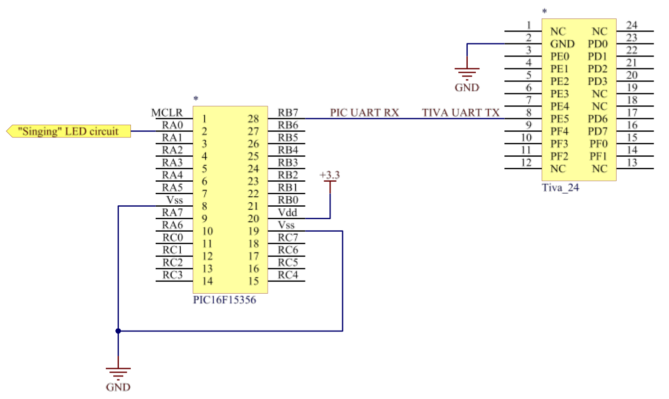
The TX line of a TIVA UART was connected to an RX line of the PIC UART in order to implement interprocessor communications. During a singing event, the TIVA would transmit a message to the PIC via UART, and the PIC would respond by blinking an LED. The TIVA is powered off of 6V bucked from one of the 7.2V batteries while the PIC was powered off of 3.3V supplied by the TIVA.
Bumpers

Four limit switches with 3.3k pull-up resistors were used for collision detection with other WHA:LEs.
Servo motor

The servo motors were powered directly from our 5 V power supply and received a PWM signal from the TIVA pins.
