Introduction
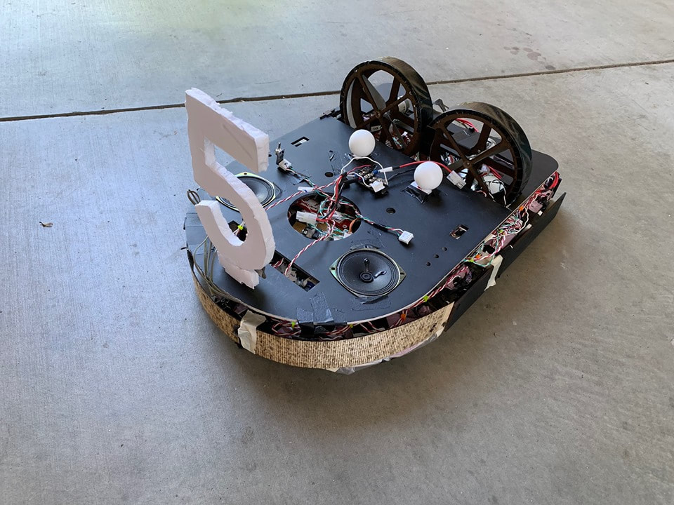
For the mechanical structure of our Hovercraft, we needed lightweight materials with strength. We identified foamcore as a perfect candidate for this. However, one layer would have been to weak to bear the weight of the all the circuits, batteries etc. So, we incorporated two layers of foamcore and designed the skirt around the two layers to also help us trap extra air. A hover fan was positioned in the center with two thrust fans near the rear end of the hovercraft. This helped us to keep the center of gravity near the center and layout the circuits around the hoverfan. Since, we were drawing a lot of current, we incorporated separate fuses for each of the circuits to ensure protection of each circuit unit. We also added a top layer to enclose all the electronics and also to serve as a cosmetic layer for our hovercraft. We used limit switches as bumpers with the front bumper designed with Kerf patterns on 1/16" birch plywood.
<Insert picture here>
<Insert picture here>
Drivetrain
Our drivetrain consists of predominantly three fans. One hover fan to ensure that the hovercraft floats on a cushion of air and two thrust fans propelling the hovercraft forward. We used differential drive (driving our two hoverfans at different speeds) to control the direction of our hovercraft. Our thrust fans were enclosed in lasercut Duron enclosures and firmly mounted to the base with L-brackets.
Bumpers
We used limit switches hidden underneath birch plywood to trigger bumps. For the left, right and rear; we used rectangular bumpers laser cut with 1/16" birch plywood while for the front bumper, we used a kerf based laser cut design which could bend in a semicircular shape. Our bumpers were mounted on the sides of pink foam which was added to the boundaries of foamcore to provide strength and also serve as a spacer for packaging the circuits within the topmost layer
Weight Distribution
Weight distribution was a real challenge for us until the last minute. Earlier, we had placed our batteries to one side of the hovercraft leading to a poor CG distribution. Thus, we moved the batteries and components around the hovercraft for an empirical determination of CG. Once, we noticed that we could get the CG near the middle with a particular configuration of component layout; we stuck to that layout and added counterweights to keep the layout if we added newer components like more batteries.
