Block Diagram
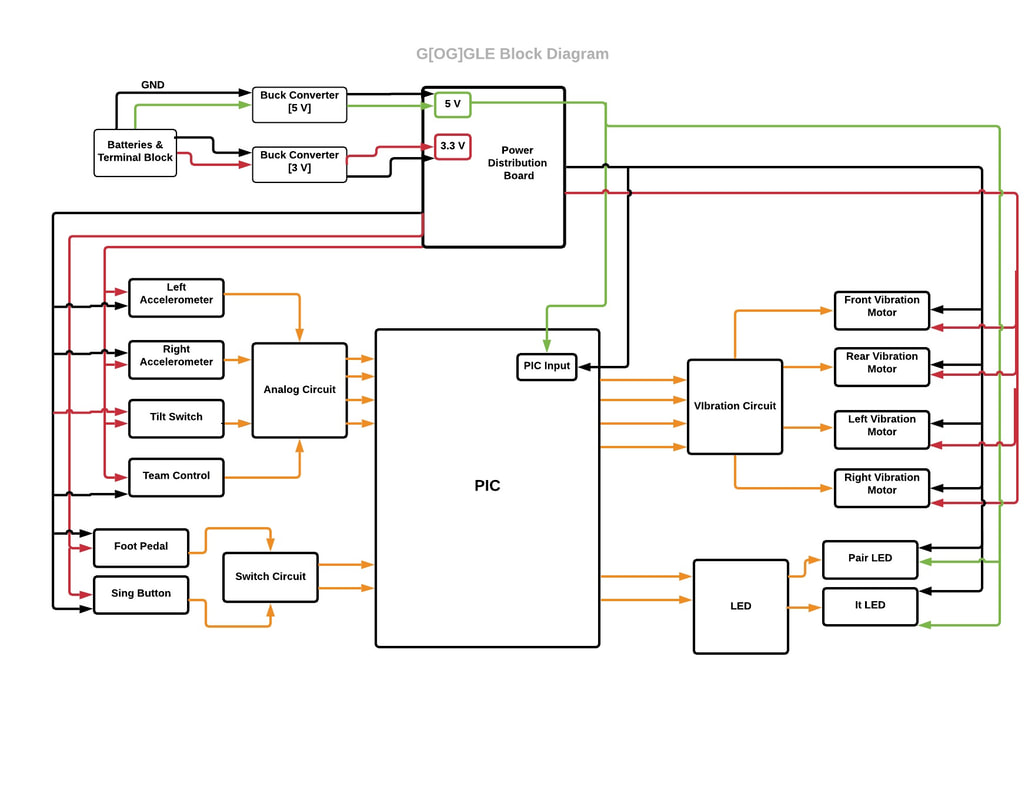
Power Distribution Board
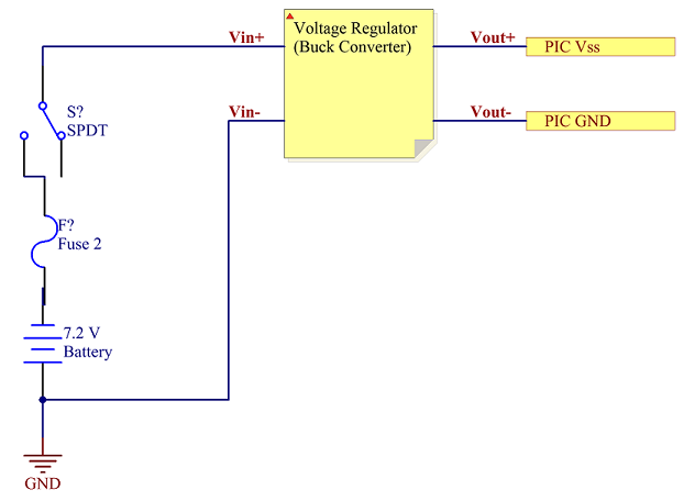
Our power distribution board was very simple for the PIC. Our PIC was powered by a 7.2 V NiCad battery which drew 3.3 V from a buck converter in series. We also used a 5 V buck converter to power some components which required 5 V like the LEDs and Tilt sensor. Moreover, we had a fuse and a SPDT switch to turn off/on the power to the PIC. We also had a 220 uF capacitor across the power rails to minimize noise.
Foot Pedal
We used the Foot Pedal as a button to drive the whale in reverse. We used a pull-up resistor to limit the current input going into the PIC. We had to use a Foot Pedal for driving backwards as our flapping action only supported three driving modes (Front , Right and Left).
Status LEDs
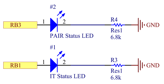
We had two status LEDs. One for displaying the PAIR Status and the other for displaying the IT Status. The LEDs were hooked up directly to the PICs with a current limiting resistor in series. We did not use an awful lot of LEDs as we wanted other modes of feedback including vibration motors for vibro-tactile feedback.
Accelerometers
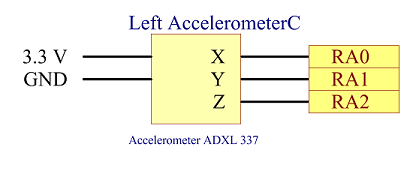
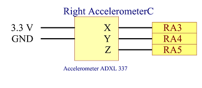
We use Sparkfun's accelerometers to help us detect wing flaps. There was not a lot of circuitry to be done for this as it directly gave out analog value of each accelerometer axis on the Port Pins. The real challenge for us was routing the wires through the Penguin Suit and making sure they were not yanked out with the users flapping their hands. We used molexes to make sure we won't unplug these while playing the game.
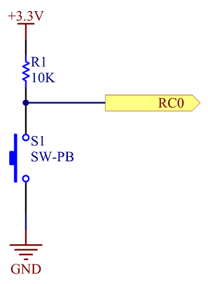
Sing Button
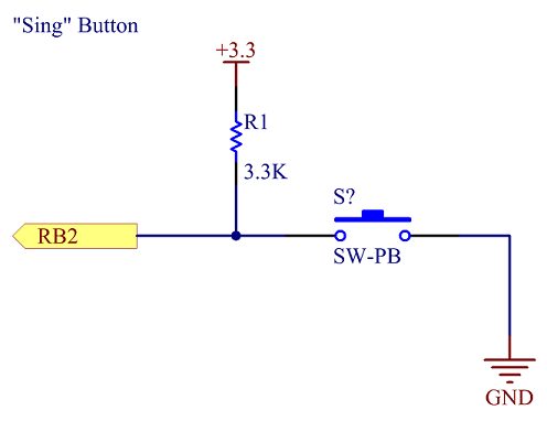
We used a pull-up resistor with a Push button to serve as input to the Port Pin to signal to the board to sing "Ed".
Team Selection
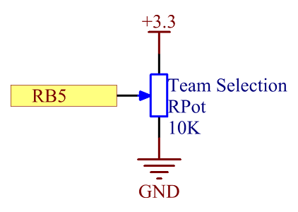
We used a 10k Potentiometer with various dial positions indicating each team to signal which team we would select using the analog value given out by the potentiometer for each dial setting.
Tilt Sensor
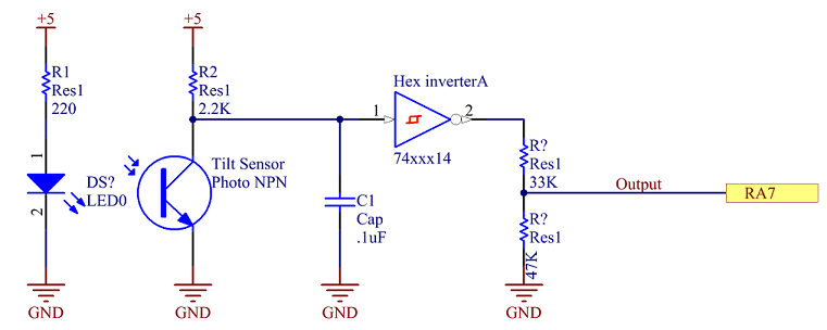
We used a tilt switch to capture the pairing status when the user turned his Bow Tie to PAIR. It contains an IR LED and an IR phototransistor, with a small freely moving beam breaking ball that only lets light pass if the device is tilted more than 30° in either direction. We leveraged this design using the ball’s inertial movement when Tilted to generate beam breaks. Once the user has shaken tilted the bow tie enough, we sent out a low signal indicating a PAIR request. The output of the tilt switch successively goes through a decoupling capacitor, a hex inverter and voltage divider to turn the noisy 0-5V signal into a clean 0-3.3V signal for the PIC.
Vibration Motors
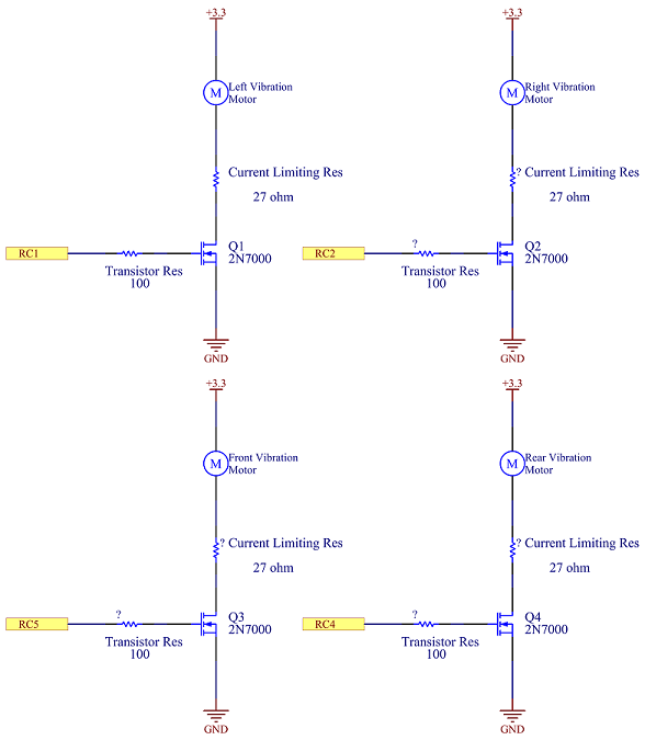
We used N-Channel MOSFETs to control the driving of each vibration motor. These small vibration motors were Powered by 3 V and received a high signal from the PIC to their gates to turn them on. We used separate MOSFETs for each of the motors as we wanted them to be turned On/Off independently. These Vibration motors served as a vibro-tactile feedback for each side of the bumpers on the WHA:LE; one for left bumper, one for right bumper, one for rear bumper and one for the front bumper.
XBEE
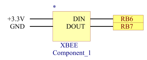
The XBEE connections were very straightforward. The DIN of the XBEE was connected to the Transmit from PIC to receive requests from the PIC. The DOUT of the XBEE was connected to the Receive from PIC to transmit requests to the PIC.
PIC Pinout
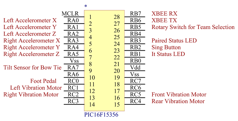
Above you can see from the Pinout above we had enough Pins on the PICs to service all the hardware. So, we only chose to keep one PIC on the G[OG]GLE to minimze components on the G[OG]GLE.
